|
Issue 14 Summer 2010
Page 4 Owners Tips
|
|
|
Spring Sailing? Glasstide comes home Ocean Dove. Barcarole Barcarole Scran Bag! members boats |
|
|
Senior leeway – What leeway?
|
|
|
I've been "off the air" for a few years - languishing in France. When the authorities there finally refused to register the road trailer for my Senior, "Mikros", and so I couldn’t move it because I couldn’t insure it...it was time to come home! Having reviewed the "Senior" parts of the EOG forum, I found a fair past interest in curing, the oft complained about, leeway in the bilge keel version of the "Senior". My reply is: what leeway? "Mikros" is a Bermudan rigged "Senior" (See elsewhere on this site about a rig modification considered in 2002) and is bilge keeled. My father built the boat in the mid-sixties; at a time when he had only just learnt to sail in a centre plate version of the same design. From his experience, he opted for bilge keels. He also designed side decks as he felt that, again, from experience, it would facilitate movement towards the foredeck. He was right. "Mikros" was first sailed on the Avon (Warwickshire) and the Severn. Tacking upstream would have been a real problem if leeway had also been one. The shallow water near the banks of these fairly narrow rivers could also have been a feature in his decision. Dad didn’t ever complain about leeway compared to his experiences in the Senior in which he had learned to sail. He made the bilge keels of ¼" steel plate. I’ve checked the original drawings and the dimensions are exactly as the wooden original (except for the thickness of course). He did not fit feet to the keel plates at that stage.
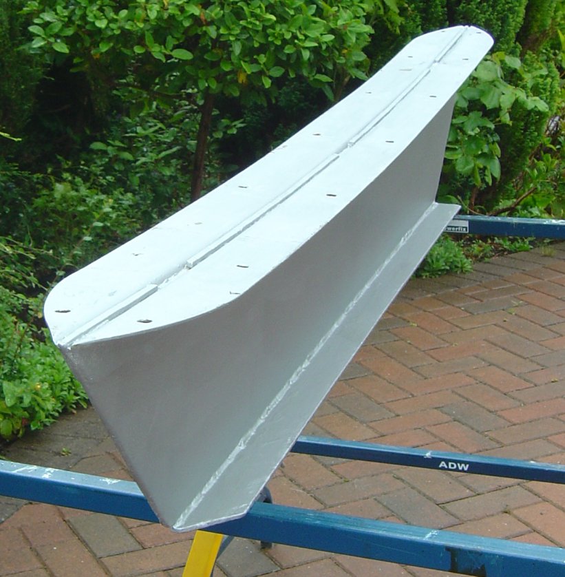
From the pictures, it can be seen that the top of each bilge keel is attached to the boat by way of two pieces of angle; the whole thing being shaped to fit the curve of the boat. I guess that if you wanted you could shape the ply pad between the keel and the underside of the boat rather than try to shape the angle iron. Dad obviously knew how to shape the latter but now can’t remember how he did it. (He’s 92 years old.)
"Well, I just bent it to fit the keel and riveted it there!!" It’s not hugely thick section angle (1/8"-ish – I’m trying to measure through several coats of primer paint!). The keel plate is sandwiched between the two angles and the three layers are riveted together. To attach it to the boat, Dad used countersunk and faired off bolts through to strengthened pads on the inside of the boat. When I re-fit this keel I will use standard coach bolts and will not expect any noticeable lessening of the performance by not turning down the heads in a lathe to make them flush with the face of the angle iron!! In the late 1980's, I took over the boat and someone, on admiring her out of the water at Lydney Yacht Club (Glos.), suggested that she needed ‘feet’. I was, by co-incidence, at the same time, ploughing my way through a degree course in applied mathematics including a year of fluid mechanics. I ran a calculator (steam driven in those days) across the idea and decided that the suggestion was a very valid one. A two inch (50mm) wide strip of steel welded at 90 degrees to the keel would seriously disrupt and slow down the sideways flow of water off the bottom of the keel. ...and it did! I’m sure that the mathematics could suggest that ...if the feet were much wider... they would be even more effective. But then other engineering issues creep in... and once you have settled into the mud at low water would the suction effect be so great...
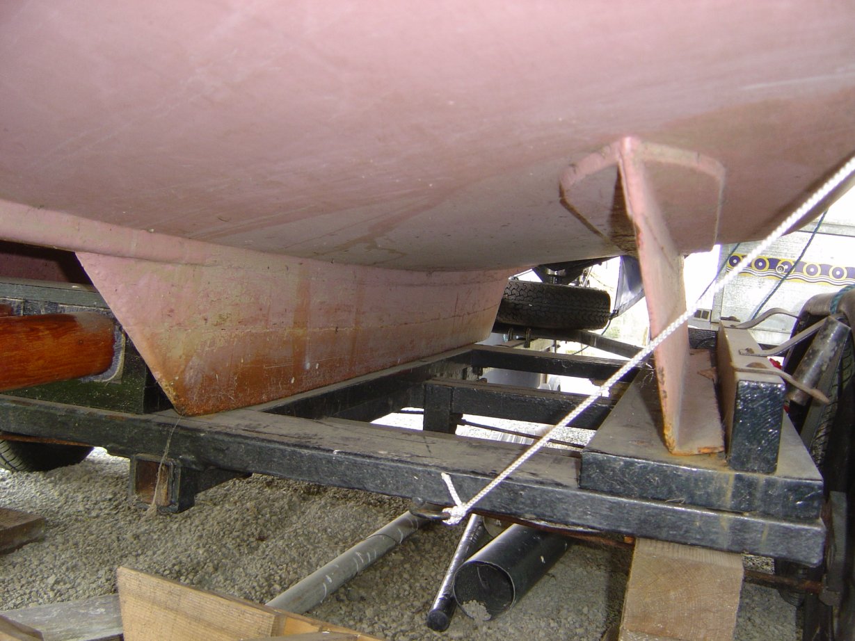
The three keels are not on a level athwart ships; with the two bilge keels being some 40 mm less deep (See the picture of the boat on the trailer). The centre stub keel is of cast iron to the original dimensions on the plan but with a faired piece of pitched pine between the keel and the cast iron. The effect is to lower the stub keel about 3 inches (75mm). The proportions can be seen in the picture. The draught of the boat is no more than 12 inches (30cms) when on even keels (which, of course, you are never on when leeway may be an issue!) I understand that Kenneth Gibbs may have proffered an alternative design for steel bilge keels for "Pau Amma" but with the stub keel being lowered some 6 inches (15 cms). She would be a bit wobbly on a hard dry out. I can’t think that my father was the sort of person to contact anyone else about any suggestions to alter the design. He would have applied his engineering background (Radar in 1939+; Huff/Duff; Blue Steel/Blue Streak; etc; and latterly Lasers.) to alter a design as he though fit. So maybe between him and the original designer, we have a working steel bilge keel alternative that’s actually been around for a number of years and will avoid suggestions of retro-fitting centre plates. Do you really want a centre plate casing and all the associated paraphernalia between you and the one you love! Leeway - what leeway? The acid test: At the 1991 Blackwater meet, I took part in the "cruise in company" and came fourth behind three Eventides: "Fiddler's Green", "Sigourd Syr", and "Saluki" and so I guess my leeway was no greater that other Seniors (who also had huge local knowledge and gunter rigs etc. etc!!) Hey, I now feel really old as that was 19 years ago... As a Post Script: The reason that the one keel is not on the boat is because they had been undisturbed for 35+ years and I wanted to see what the bolts were like. In fact they were fine and if there had to be any criticism it would be that the bolts were marginally more effected by corrosion where they had been next to the wood; i.e. the marine ply and the oak load spreading pads on the inside. I must ensure that I either push paint up into that area or ensure more sealer around the threads. But if they last another 40 years it won’t be me worrying about their condition... Geoffrey HYDE FYNN "Mikros" YMS 779
|
|